Explaination
This part shows the significant issues we met during this project and the solutions to deal with these problems. Moreover, the accomplishments and features are also introduced in this part.
There are three issues & accomplishments I want to mainly focus on.
1. Communication Between Two Boards
We can choose either serial communication or parallel communication to achieve communications between two boards. Both modes have their advantages and disadvantages. The parallel mode offers the advantage of faster loading of the registers, but with the disadvantage of requiring more interconnect traces. The serial mode offers simplicity, but with less speed.
Several methods are considered to deal with communications between two boards, such as I2C, UART and GPIO. However, I2C is not available between twp RP2040’s communication as RP2040 cannot be slaves. We also tried UART to transfer control signals but the trasfered data is not stable maybe due to the wire connection. Thus, we finally chose to use RP2040’s GPIO pins to output instead of others, as using GPIO for parallel communications provides more stability and it is easy to realize.
2. Image Processing
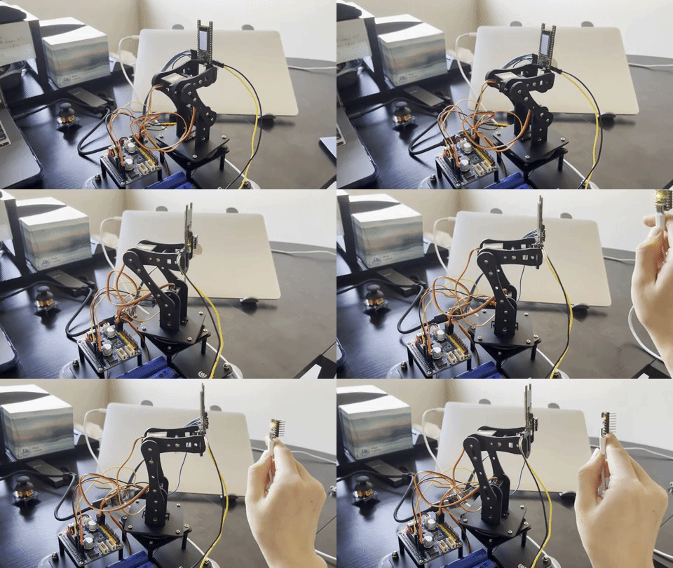
As I mentioned before, the camera module can only read gray value. If it is exposured to an environment with high light level, it will read every bright things and even things which are able to reflect light as white (grey value = 255), instead of reading the brightest led as white due to its low brightness threshold. This is an important issue as if we cannot solve it, this robotic arm can only operate properly in relatively dark environment. This is a big limitation to the demo of our project!!! And if the image processing doesn’t well, it sends wrong control message to RP2040 and leads to a mess like this:

If we want to obtain better performance on demo day, there are two possible methods to deal with this issue:
- Change the previous idea to detecting some specific pattern.
- As the brightness level of led is much higher than the environment, we may change the parameter of the camera module (like exposure gain)
However, I still want to focus on changing the camera parameters, after reading the datasheet of HM01b0, I find something maybe helpful – Black Level Corresction!

How to define BLC?
Black level correction, also known as black level compensation or black point correction, is a feature or function in some cameras or image processing systems that adjusts the brightness or intensity of the darkest parts of an image. It is often used to compensate for the differences in the way that different cameras or sensors capture or represent black, which can affect the overall contrast and tonal range of the image.
Black level correction typically works by adjusting the brightness or contrast of the image in the darkest areas, which can help to improve the overall balance and contrast of the image. This can be especially useful when shooting in low-light conditions or when using cameras or sensors with different characteristics or sensitivities.
To apply black level correction to an image, you can typically use a photo editing or image processing software program that offers this feature. Many programs offer automatic black level correction, which can be applied with just a few clicks, or you can adjust the settings manually to achieve the desired effect.

Implementation & Performance
After finding the BLC parameter, I increased this parameter to get better performnce and it works suceessfully! This camera can find the led even in a high level light environment!
The modified code:
    {0x1003,0x8f}, // 0x08
    {0x1007,0x8f}, // 0x08
Presentation:

3. Dynamic Initial State
To increase the interestingness of the demo performance, a dynamic initial state is designed. The robotic arm rotates vertically and horizontally in turns, once it catch the brightest point, it will stop and follow it. If it doesn’t detect the led point for a while, it returns to the dynamic initial state!
The code to realize this state:
initialcounter += 1

            if (initialcounter > 99):
                if (initialcounter == 100):
                    init_smooth()

                print(str(initialcounter) + ' and ' + str(counter))
                # horizontal rotation
                if (counter < 3):

                    if (servo0 == 80):
                        counter += 1
                    if (jud == 0 and servo0 > 15 and counter < 3):
                        servo0 -= 1
                        if (servo0 == 15):
                            jud = 1
                    elif (jud == 1 and servo0 < 145 and counter < 3):
                        servo0 += 1
                        if (servo0 == 145):
                            jud = 0


                # vertical rotation
                elif (counter > 2):
                    if (servo2 == 160):
                        counter += 1
                        if (counter == 5):
                            counter = 0

                    if (jud == 0 and servo2 > 120 and counter < 5):
                        servo0 -= 1
                        if (servo0 == 120):
                            jud = 1
                    elif (jud == 1 and servo2 < 180 and counter < 5):
                        servo0 += 1
                        if (servo0 == 180):
                            jud = 0

            time.sleep(0.01)
The final presentation:
