Explaination
This part mainly introduces the components applied in this project, the assembling details, block diagram of the whole system, RP2040 operating environment and link to our final code.
1.1 Components Intructions
Required components of this project:
-
Robotic Arm Kit

There are five servo motors on this kit, but in order to cut down the complexity of motion design, we only applied three servo motors to realize two dimentional manipulating.
-
Arm HAT
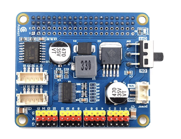
The compatible micro controller of this hat is Raspberry Pi 3/4. Since the pins of Raspberry Pi 3/4 and Raspberry Pi Pico are not compatible, it is necessary to reconnect the circuit according to the circuit diagram in the data package.The programming method of Raspberry Pi Pico is also different from that of Raspberry Pi 3/4, so the corresponding program needs to be modified.Using a Raspberry Pico instead of a Raspberry Pi 3/4 is doable, but takes more time.
From its datasheet, it is found that actually there are two main chips on this arm hat: one is PCA9685 which is used to drive the servo motors, while another one is PCF8591 which is an ADC.
-
QT PY RP2040

In this project, RP2040 is used to take the place of Raspberry Pi 3/4. After reading the datasheets of the arm hat and modified the code, it drives the board and controls the servos successfully.
-
PICO4 ML

The PICO4 ML is a single board microcontroller powered by RP2040 and it is applied to dealing with image processing part in this project.
A QVGA camera module with ultra-low power consumption, configurable 1-bit video data serial interface with video frame and line sync.
The small TFT display at the back of Pico4ML is a 160×80 LCD, it’s connected to the board through the SPI interface, you can do a live preview of the camera, or display the results of any of the your ML models in real-time.
-
Power Supply

Totally three 18650 lithium batteries are applied in this project, two of them are connected in series to power the PCA9685 while the last one is applied to power the Pico4 ML to increase its flexibility on the robotic arm.
Summary Table:
| Number | Components |
|---|---|
| 1 | Simple Robotic Arm Kit |
| 2 | Driver Board (PCA9685) |
| 3 | QT PY RP2040 |
| 4 | PICO4 ML |
| 5 | Wires |
| 6 | Power Supply |
1.2 Assembly Details

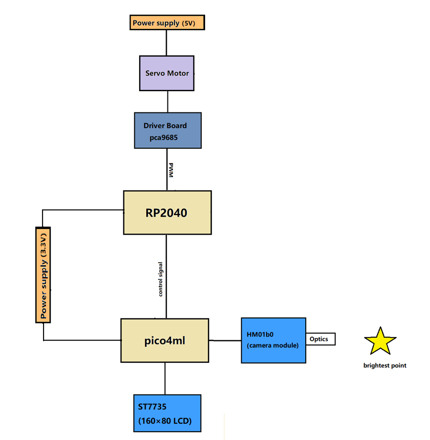
1.3 Block Diagram
1.4 QTPY RP2040 & PICO4 ML
As mentioned above, in this project, RP2040 is applied to send control signal to the driver board PCA9685 while PICO4 ML is applied to do the image processing part.
QTPY RP2040
We use micro python to program RP2040 as the library of PCA9685 is easy to apply and it also simplifies the motion control code. RP2040 recieves the control signal from PICO4 and responds by sending corresponding control signal to PCA9685. The communication between two borads is through GPIOS.
PICO4 ML
There are two important modules on the PICO4 which are: HM01b0 (a camera module) and ST7735 (a 160×80 LCD). PICO4 is programmed by C in this project. The camera module is applied to capture the image while the lcd provides real-time display.